Basics Of Gate Operators
For our first blog on gate openers, let's start with the basics. This is by no means intended to be a complete synopsis of all gate openers but this is a broad overview of opener types and some of the peripheral accessories our industry deals with.
Types Of Gate Operators
(A) Mechanical Operators
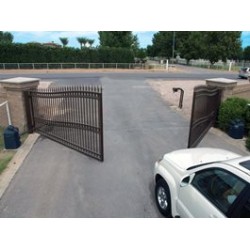
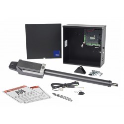
(1) Worm Driven also called Actuators. This type works by changing the length of the distance between the gate bracket and the post bracket. Only works on swinging gates. One of the easiest to install but generally has the shortest warranty.
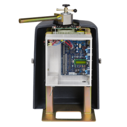
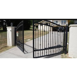
(2) Pad Mounted Swing Gate Operator - This type using an articulating arm to pull the gate open and push the gate close. They handle wind load and other obstructions better than an actuator. And most commercial operators have at least a 5-year warranty.
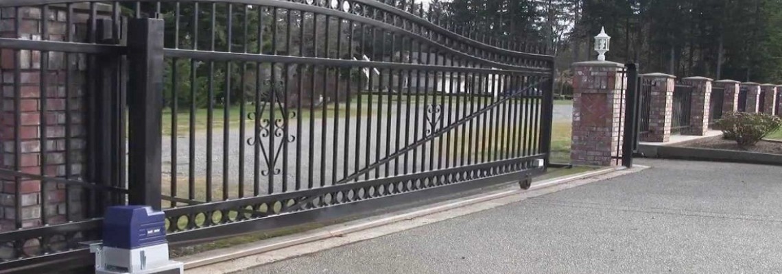
(3)Sliding Gates -There are two types of operator chain-driven or rack/pinion style. They both work by pulling either the chain or rack past the operator to pull each one end of the gate towards the gate operator.
(4) Barrier Gates - These are spring or weight counterbalanced to raise and lower a beam across a roadway for traffic control.
(B) Hydraulic
(1) Have the advantage of being able to produce more power than their mechanical counterparts. And since they have less moving parts they usually last longer and can be rebuilt most of the time when they go down. The most common types are the actuator and in-ground swing gate operator.
Safety
(A) UL 325 2016
(1) UL 325 is the safety standard for the manufacture and installation of gate operators by Universal Laboratories.
(2) Some of the main requirements for gate operators are
- The system must have an inherent entrapment protection system that when set properly will cause the gate to reverse a few inches and then shut down until it receives a command that resets the operator.
- New to the requirements this year is that all gate operators must have a monitored photo eye or monitored gate edge. What this means is that if the operator does not detect the photo eye or gate edge the operator will not run.
(B) Safety Devices
(1) Internal Devices
- Inherent system – Two different methods that gate operators use. One method works by monitoring the motors amp usage and a sudden change will activate the system to stop the operator and reverse the gate a few inches. The other method is by monitoring the rotation of the motor where an unexpected stop will stop the operator and reverse the gate a few inches. Both methods are triggered by the gate having hit or think it hit something(ie high winds) with at least 40lbs of resistance or enough to stop the gate.
(2) External Devices
- Photo Beams - Non-Monitored – Most gate operators used the common and normally open relay on a photo beam to indicate an obstruction which caused the relay to close. This was the industry standard until January 12, 2016, when the current version of UL325 went into effect. Monitored Beams – Depends on the brand of the gate operator. The four most common methods are 10K resistant, NC, 2 wire pulsed 2 freq, and 2 wire pulsed 3 freq. Gate operators requiring monitored beams can not be operated without a monitored beam connected to the unit.
- Gate Edges - Typically are placed on the leading edge of the gate to detect an obstruction by bumping into it. Edges are also sometimes placed on the trailing edge and the guideposts for additional protection. Gate Edges are contact safety meaning the gate edge has to make contact with the obstruction before causing the gate to reverse. Monitored gate edges meet current UL guidelines for a secondary safety system.
- In-ground loops - Used for free exit and the detection of vehicles in the path of the gate. They are placed in a large rectangle in the drive usually 4'x8' or 6'x12' around 4' outside the swing of the gate on both sides of the gate. Does not meet UL standards for a safety system.
- Exit Probes - Not a safety device only used for free exit. Unlike a loop that detects the presence of a vehicle loop probes detects a shift in the magnetic field caused by a moving vehicle through the field. Once a vehicle stops moving it becomes invisible to the probe. Does not meet UL standards for a safety system.
Control Devices
(A) Remotes
- Wireless devices used to operate the gate from a distance of up to 100' away. The two most common types are dip switch (Multi-Code) and rolling code. Dip Switch has switched in both the receiver and remotes that have to match. Rolling code remotes have to be synced to the receiver.
(B) Keypad
Two Types Of Keypads
- Hard wired to the operator, most have full-size keys and a metal housing. Usually more weather resistant than wireless. Most can also handle 100+ codes and some of these codes can be latch codes to override the auto-close timer and hold the gate open.
- Wireless has to be synced to the receiver inside of the gate operator. Latch codes will not work with wireless keypads.
(C) Telephone Entry
Types of Telephone Entry
- Single Family with landline phone to the house. This type of telephone entry will use the phone line going inside of the house to ring the phones inside the house to request entry. Most of these systems can also be programmed to call an outside number like a cell phone if no answer from the house line.
- Single Family without a line. This would require the use of a cell phone entry system. When the call button is placed the unit would call a programmed number to request entry to the property.
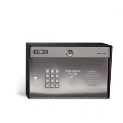
- Multi-Family – These are where a person pulls up and selects a person from a menu or enters the residents calling code to call the person to gain entry. These systems are generally hardwired to a landline, but recent improvements in the systems have made it possible to connect these systems with a cellular interface unit so no landline is needed.
(D) Card Readers
- Card Readers can be stand-alone units or part of a multi-door control system. But basically, the user taps or swipes a card across the reader and if authorized the reader sends an activation command to the gate operator.
(E) 7-day Timers
- Used to open and hold open a gate at a programmed time and day for a certain length of time.
(F) Fire Department
- Yelp or Siren Sensors open the gate when the unit hears a siren off of an emergency vehicle.
- Chain releases are used on sliders to manually release the chain on the rear bracket so that the gate can be moved by hand.
- Fire Boxes have a switch inside that when the door is opened the gate receives a command to open no matter what.
- Fire Switches is an electronic key switch that is installed in a box or telephone entry system to activate the gate by the fire department.
- Knock locks can only be purchased from the Knok Lock company and the customer has to get the keying code from their local fire marshal
- There is no set standard for the type of system employed by fire department across the country. The customer will need to call their local fire marshal to find out what the requirements are in their area.
History of Gate Operators
Generation 1
(1) No electronics – Used relays and contractors to control operator
(2) AC Motors usually 110V or 220V
(3) No built-in safety reversal in operators. Primary safeties were slipped clutches.
(4) Primary Brands were
- Link
- Stanley
- John Green
Generation 2
(1) Introduction of Electronic Control Boards into Gate Operators
(2) Still using AC high voltage motors
(3) Safeties still primarily slipped clutch-type systems.
(4) Primary Brands were
Generation 3
(1) Prime difference is the introduction of the first UL 325 requirements. Slip clutches were replaced with inherent detection systems or motor rotation sensors.
(2) Still using high voltage systems battery backups were if available half-speed open only systems
(3) Primary Brands
Generation 4
(1) The introduction of the hybrid gate operator that runs off both high and low voltage power sources. These operators had built-in battery backup systems that allows the unit to run normally during a power outage.
(2) DC motors replaced the older AC motors.
- Operators now have a soft start/stop capacity
- The elimination of belts and the heavy gear reducers
- Energy-efficient motors
Generation 5
(1) Same as generation 4 operators but with the addition of monitored safety devices for pedestrians per UL 325 2016.

